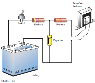
A schematic is described as a drawing that schematic drawings, straightforwardly illustrates things through the use of symbols. A schematic diagram is a representation of a process, device, or other object’s components using abstract, frequently standardized symbols and lines.
Illustrate simply the essential components of a system, while certain features may be exaggerated or inserted to aid in the system’s comprehension.
Schematic diagrams exclude features that are not important for interpreting the information conveyed by the diagram. For instance, a schematic diagram of an electrical circuit illustrates how the wires and components are linked, but does not include images of the circuit itself.
Schematic Diagram
Additionally, schematic drawings might differ in their degree of abstraction. While most diagrams are formed entirely of abstract symbols and lines, some are semi-schematic and feature more realistic aspects. Certain diagrams may additionally include text, for example, when a process comprises numerous unstandardized pieces.
To put it another way, a schematic drawings is a simplified drawing that makes use of symbols and lines to communicate critical information. For instance, if you’re riding the subway, you may see a “map” of all the stations along the route, but that map will omit any roads or buildings you may pass. The complete subway system may be shown in this fashion as a series of variably colored lines denoting the various subway routes, with dots denoting the stops along the lines.
Though schematic diagrams are most frequently linked with electronics, you have very certainly met several similar diagrams, such as the one above, even if you have never had to connect a circuit. The following are a few examples of the numerous schematic diagrams that you may meet in your profession or study.
Electronic Schematic Diagrams
Typically, schematic drawings are used to depict electrical circuits. Also known as wire diagrams or circuit diagrams, these diagrams illustrate the connections between the various components of a circuit. In these diagrams, lines indicate connecting wires, while standardized symbols called electrical schematic symbols represent additional elements like resistors, bulbs, and switches.
In electronics, having a schematic diagram on hand can assist a user in designing a whole circuit before construction or troubleshooting an electronic that has failed to function.
Schematic diagrams may also be used to illustrate the overall operation of an electrical device without going into depth about the hardware or software employed in the device. To illustrate how a computer displays the text you enter on a screen, for example, you could use a schematic diagram that depicts the flow of information from the keys you press to a word processing application and eventually to the computer screen.
Manufacturing Schematic Diagrams
Additionally, schematic drawings may be used to illustrate machinery. For instance, an automobile engine may be shown in a textbook as a collection of shapes indicating the relative positions of the various components. A schematic sketch may also be generated by an engineer while they develop the machine to ensure that they fully understand how the components interact and can make any required modifications before creating the real system.
